SPHARM-PDM User Tutorial
Authors: Laura Pascal, Jonathan Perdomo, Martin Styner, Hina Shah, Beatriz Paniagua
Collaborators:



SPHARM-PDM Tool Description
Shape Analysis allows to precisely locate morphological changes between healthy and pathological structures. Spherical Harmonic Representation Point Distribution Models (SPHARM-PDM) tool is used to compute densely sampled correspondent point based models that allow performing 3D structural statistical shape analysis.<
The inputs are binary segmentations which are converted into corresponding spherical harmonic descriptions (SPHARM) and then are sampled into triangulated surfaces (PDM).
The SPHARM-PDM tool consists on three steps:
Step 1 : Preprocessing uses SegPostProcess CLI
Input: Binary Segmentation
Output: Binary 3D Image
Step 2 : Parameterization uses GenParaMesh CLI
Input: Binary 3D Image
Output: Surface Mesh + Parameterization sphere
Step 3 : SPHARM-PDM uses ParaToSPHARMMesh CLI
Input: Surface Mesh + Parameterization sphere
Output: SPHARM Coefficients + Aligned Surface Meshes
Step 1: Post Process Segmentation
This step will ensure spherical topology of the segmentations by filling any interior holes and by applying two smoothing operations and extract a single label or a label range
Re-sample the label data to ensure an isotropic resolution and a relative fine resolution
Input : Binary Segmentation
Output : Binary Segmentation File: *pp

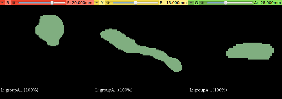
Figure : Input/Output of SegPostProcess CLI
Step 2: Generate Mesh Parameters
This step will extract the surface of the input label segmentation and create an area conforming mapping of the surface mesh to a unit sphere.
Note : If this step reports bad Euler number, it will mean that the extracted surface is not a spherical topology. spherical topology has an Euler number of 2.
Input : Binary 3D Image File *pp
Outputs : Parametrization sphere + Surface Mesh Files: *para.vtk + *surf.vtk
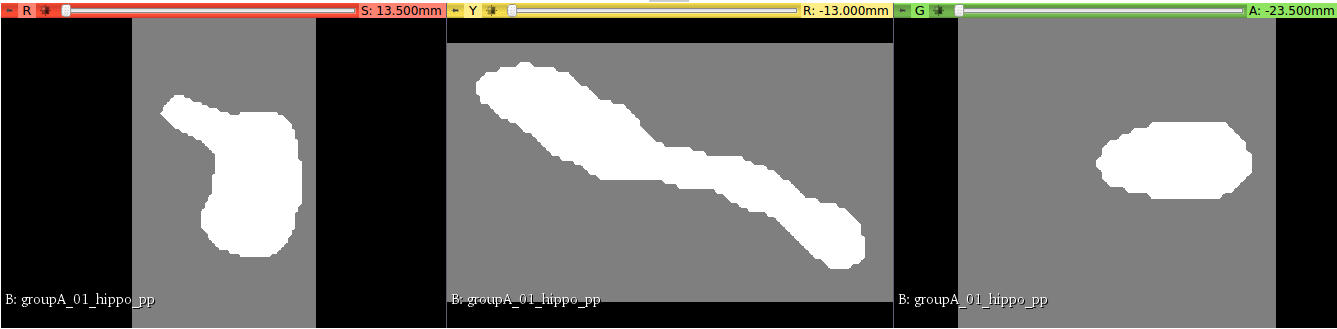
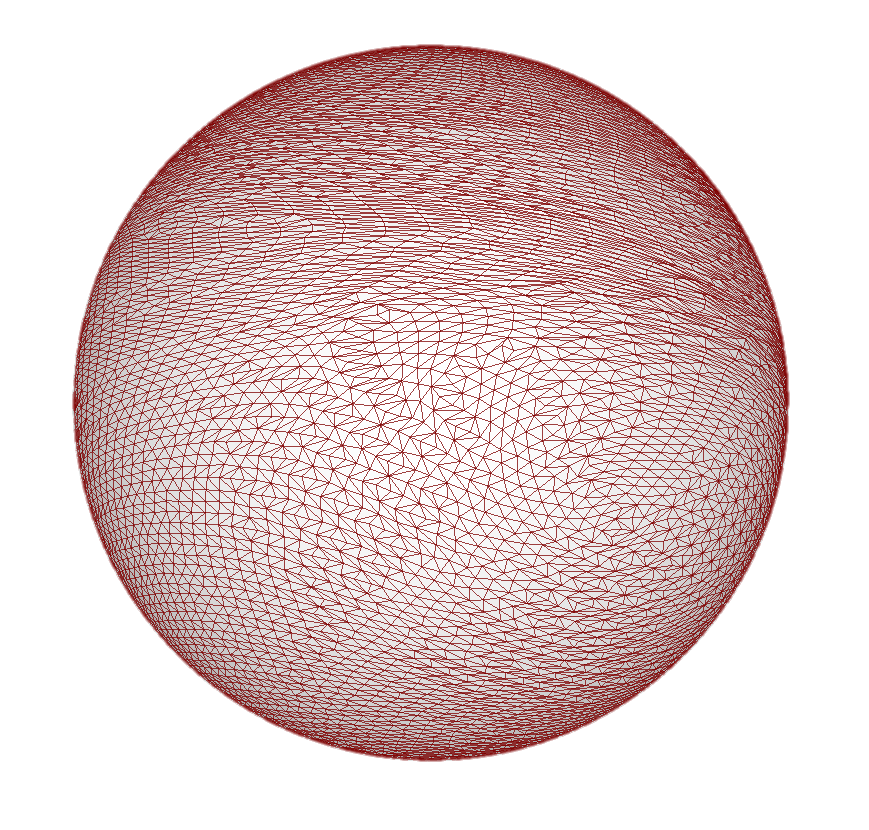
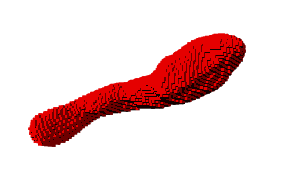
Figure : Input/Output of GenParaMesh CLI
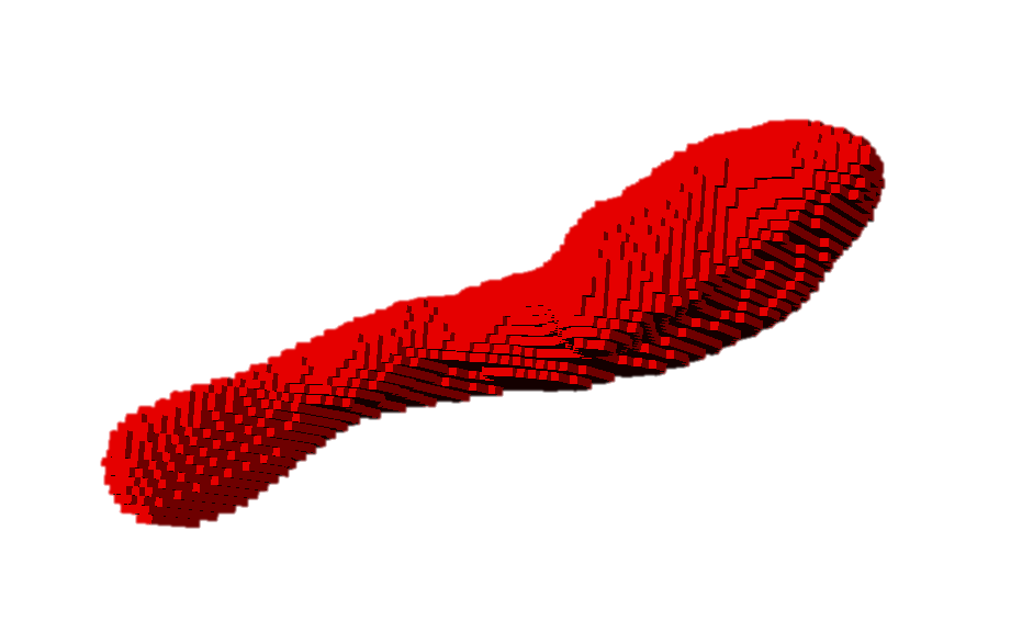
Figure : *surf.vtk is a surface approximation of the input file which represents the original voxel mesh: the cubes show the voxel delineation. The surface will appear blocky because of it is the result of a marching cubes algorithm.
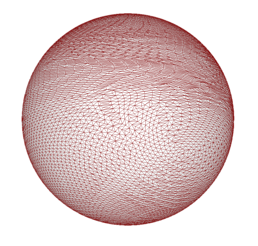
Figure : *para.vtk is a the spherical mapping of the *surf.vtk file. The sphere is an unit sphere (diameter = 1)
Step 3: Parameters to SPHARM Mesh
This step will:
Compute the SPHARM-PDM representation
Compute the spherical harmonic description
Sample into a triangulated surface
The two main parameters for this step are:
The degree for SPHARM computation
The subdivision level for the icosahedron subdivision
Resolves issues of correspondence pose and alignment
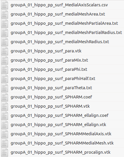
Figure : Input/Output of ParaToSPHARMMesh CLI

Figure : Comparison between the surface mesh generated by the Generate Mesh Parameters step (red) and the SPHARM-PDM output * SPHARM.vtk (blue):
Note : This figure shows how the final correspondent PDM represents the geometry of the structure without fitting the voxel mesh obtained from the binary segmentation
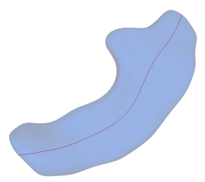
Figure : Visualization of *SPHARMMedialAxis.vtk (red) and *SPHARMMedialMesh.vtk (blue)

Figure : __*para.vtk __ is a sphere with a icosahedron subdivision of 10.
Note: The sphere has 1002 points and the triangulated surface generated will have the same number of points that this sphere. This file includes the spherical parameters ( φ,θ ) at each point.
This sphere is also a unit sphere (diameter = 1)

Figure : Visualization of *para.vtk (blue) and *SPHARM_Ellalign.vtk (red) which is aligned with the *para.vtk sphere:

Figure : Spherical parameters color map files

Figure : Comparison of the spherical parameters color maps containing in the *SPHARM.vtk in ShapePopulationViewer tool:
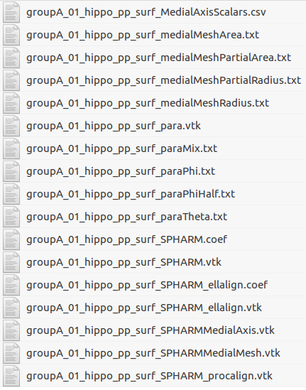
Figure : Medial mesh parameter color map files

Figure : Comparison of the Medial mesh parameter color maps containing in the * SPHARMMedialMesh.vtk in ShapePopulationViewer tool
Installation of SPHARM-PDM Tool
SPHARM-PDM tool can be used with two open-source software platforms: * SlicerSALT : which is the dissemination vehicle of powerful shape analysis methodology. This software is a light-weight, customized version of 3D Slicer. It contains SPHARM-PDM as a module . * 3D Slicer : which is an open-source and free software platform for medical image informatics, image processing, and three-dimensional visualization. SPHARM-PDM can be downloaded as an extension .
Installation via SlicerSALT
Download the SlicerSALT packages for your respective operating system from the SlicerSALT website and install it.


Installation on 3D Slicer
Download 3D Slicer packages for your respective operating system on the 3D Slicer website and install it.
In 3D Slicer, open the Extension Manager
In the Install Extension tab, select SPHARM under Categories
Under SPHARM-PDM , select the Install button and restart Slicer when prompted
For quality control, we analyze our SPHARM-PDM outputs with Shape Population Viewer extension. Shape Population Viewer can be installed as a 3D Slicer extension or as an external binary. This module is included as part of the SlicerSALT package.
To install Shape Population Viewer as a 3D Slicer extension :
Open Extension Manager , in the Install Extensions tab, select ‘ Shape Analysis’ under Categories
Select the appropriate Install button and restart 3D Slicer when prompted
To install Shape Population Viewer as an external binary :
Download ShapePopulationViewer package for your respective operating system on NITRC website
In 3D Slicer, open Application Settings in the Edit Menu. On the tab Modules , __Add __ the folder where ShapePopulationViewer is stored
Restart 3D Slicer

SPHARM-PDM tool can be used by two different ways:
As command-line tool through the terminal thanks to SlicerSALT
As a module of SlicerSALT or 3DSlicer
SPHARM-PDM Command-Line Tool
SPHARM-PDM method can be run on several cases through a terminal thanks to two files included in the SlicerSALT package:
SPHARM-PDM-parameters.ini which allows the user to specify the inputs, outputs and the parameters of the SPHARM-PDM tool
SPHARM-PDM.py python script which will apply SPHARM-PDM method on the given input cases with the parameters specified in the SPHARM-PDM-parameters.ini file
Location of the SPHARM-PDM.py and SPHARM-PDM-parameters.ini files:
On Linux and Windows: share/Slicer-4.7/CommandLineTool
_On MacOs: Open the SlicerSALT Contents _
🡪 Contents/share/Slicer-4.7/CommandLineTool

Step 1 : Modification of the SPHARM-PDM-parameters.ini file by specifying the __input directory path __ containing the input cases and __the output directory path __ where the SPHARM-PDM outputs will be stored.
The others parameters can also be modified to apply SPHARM-PDM to a particular case.

Step 2 : Launch SPHARM-PDM method with the following command-lines:
On Linux and Windows:
$cd path-to-the-SlicerSALT-package
$./SlicerSALT –no-main-window –python-script share/Slicer-4.7/CommandLineTool/SPHARM-PDM.py share/Slicer-4.7/CommandLineTool/SPHARM-PDM-parameters.ini
On MacOs:
$cd path-to-the-SlicerSALT-package/SlicerSALT.app/Contents/MacOS
$./SlicerSALT –no-main-window –python-script ../share/Slicer-4.7/CommandLineTool/SPHARM-PDM.py ../share/Slicer-4.7/CommandLineTool/SPHARM-PDM-parameters.ini
SPHARM-PDM Module
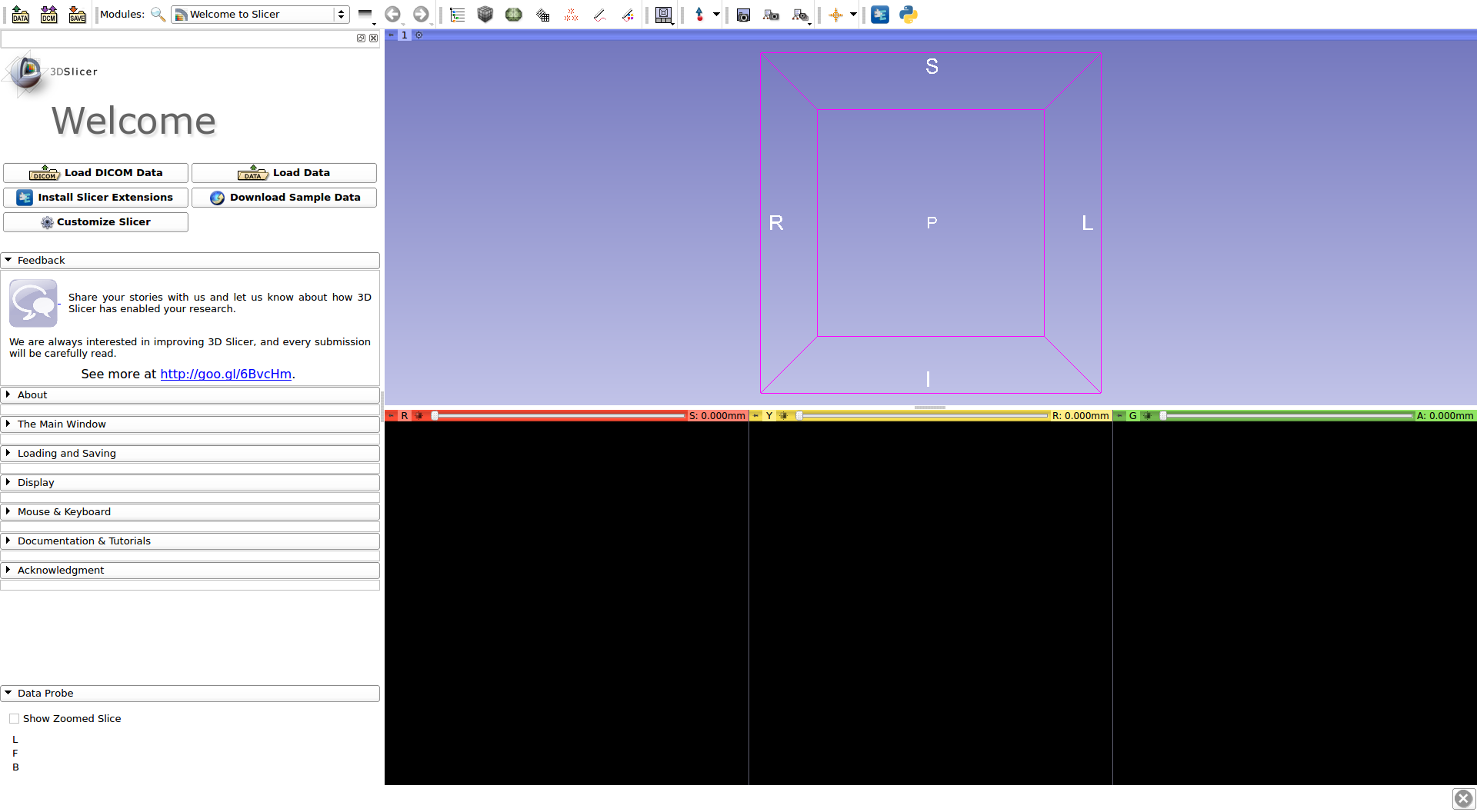
In 3D Slicer or in SlicerSALT, select Shape Analysis Module from the Modules drop-down menu ( Category: SPHARM) or on the Search bar.


Setting up Input/Output Directories
Group Project IO
For Input Directory , select the folder which contains the input data
For Output Directory , select the folder where the outputs of each step will be stored

Input/Output Data
The input directory contains the input data which can be:
Label map volumes (.gipl, .gipl.gz, .nii, .nii.gz, .nrrd, .mgh, .mgh.gz, .mhd, or .hdr)
Models (.vtk, or .vtp)
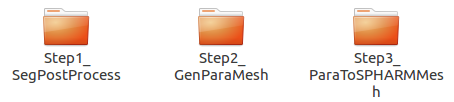
The output directory will contain SPHARM output data sorted in three different folders for each of the three steps:
Step1_SegPostProcess for the Post Processed Segmentation step
Step2_GenMeshPara for the Generate Mesh Parameters step
Step3_ParaToSPHARMMesh for the Parameters to SPHARM Mesh step
Features and Parameters
Common to all tabs
The Overwrite option: this option is available for the three steps of Shape Analysis Module :
If this option is not selected for one step, it will skip the step if the output data were previously computed and stored in the output folder of this step:
Folder Step1_SegPostProcess for the Post Processed Segmentation step
Folder Step2_GenMeshPara for the Generate Mesh Parameters step
Folder Step3_ParaToSPHARMMesh for the Parameters to SPHARM Mesh step
If this option __is selected __ for one step, all the files in the output folder of this step will be removed and the step won’t be skipped.
Post Processed Segmentation tab
Rescale option : The X, Y and Z spacing parameters (sx/sy/sz) determine the resolution in which the data will be processed for each axis (in millimeters)
Label Number option : First extraction of the specified label before to apply the post processing step

Generate Mesh Parameters
Number of iterations : Higher number of iterations will improve the accuracy of the mapping of the surface mesh to a parameterization sphere

Number of iterations |
|---|
5 |
1000 |
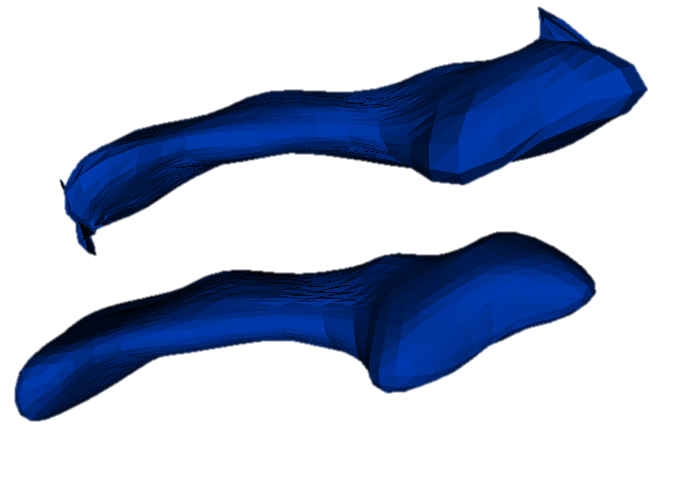
Figure : *SPHARM.vtk generated with 5 iterations (top) and 1000 iterations (bottom)
Note : Higher number of iterations will produce better representation results.
Parameters to SPHARM Mesh
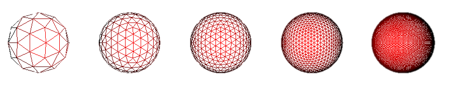
Subdivision Level value : Icosahedron subdivision allows for linear, uniform sampling of the object by referring to its spherical parameterization. The SubdivLevel value sets the level of the subdivision factor that will be used. Improving this value results in a SPHARM mesh with more points.
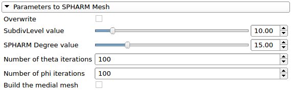
Parameters to SPHARM Mesh
Subdivision Level value :
__Figure: __ *para.vtk generated with 5 subdivision different (left to right : 2 – 4 – 6 – 10 - 20)
Subdivision Level |
2 |
4 |
6 |
10 |
20 |
|---|---|---|---|---|---|
Number of Points |
42 |
162 |
362 |
1002 |
4002 |
Parameters to SPHARM Mesh
Subdivision Level value :
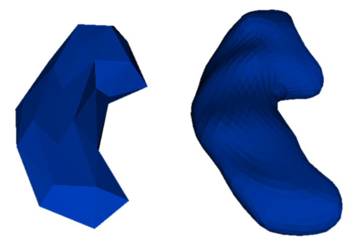
Figure : *SPHARM.vtk generated with a subdivision level of 2 (left) and 10 (right)
Note : Higher subdivision level value will result in a smoother surface mesh.
Subdivision Level |
2 |
10 |
|---|---|---|
Number of points |
42 |
1002 |
Parameters to SPHARM Mesh
SPHARM Degree value represents the degree of the spherical harmonic series used on the data. Changing this value results in different levels of detail of the object.
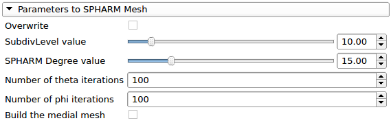
Parameters to SPHARM Mesh
SPHARM Degree :
SPHARM degree |
|---|
1 |
3 |
5 |
10 |
25 |

__Figure: __ *SPHARM.vtk generated with different SPHARM degree (left to right: 1 – 3 – 5 – 10 – 25)
Note : A higher SPHARM degree value will result in a surface mesh with more details.
Parameters to SPHARM Mesh
Build the medial mesh: This option will compute the mean latitude axis associated with the data if checked. The Number of theta/phi iterations corresponds to the number of samples used in the medial mesh computation 1 .
1. Paniagua B1, Lyall A, Berger JB, Vachet C, Hamer RM, Woolson S, Lin W, Gilmore J, Styner M. (2013). Lateral ventricle morphology analysis via mean latitude axis. Proc SPIE Int Soc Opt Eng. 2013 Mar 29;8672. pii: 2006846. <http://www.ncbi.nlm.nih.gov/pubmed/23606800>

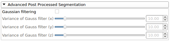
Advanced Post Processed Segmentation
Gaussian filtering : A Gaussian filter will be applied during the preprocessing step if this option is checked.
Advanced Parameters to SPHARM Mesh
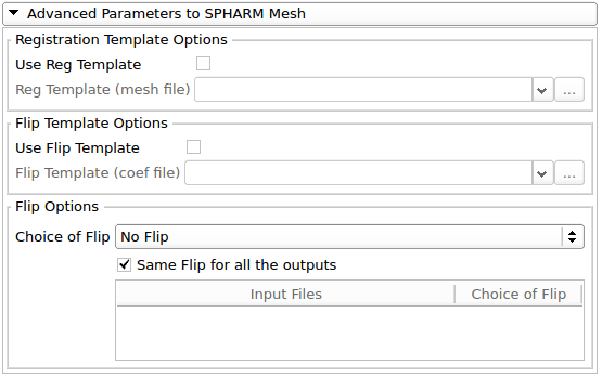
Registration template Options : This option allows to have a rigid-body Procrustes alignment i.e. the *SPHARM_procalign mesh generated by the tool will be aligned with the registration template (VTK file) by applying, if needed, a rigid transformation (which uses only translation and/or a rotation).
Advanced Parameters to SPHARM Mesh
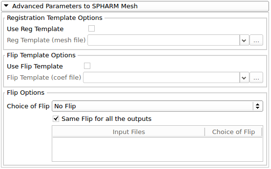
Flip template Options : If Use Flip Template is checked, a Flip Template is used to test all possible flips of the parametrization along the first order ellipsoid axis and select the one whose reconstruction has minimal distance to the flip-template.
Advanced Parameters to SPHARM Mesh
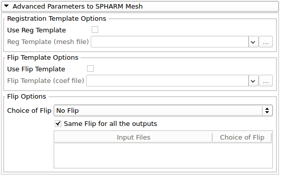
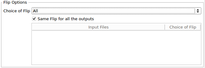
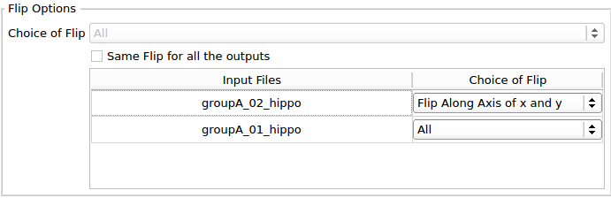
Flip Options : This option allows an optional flipping of the parametrization specified by the user.
Advanced Parameters to SPHARM Mesh
Flip Options : To apply the same flip option for each case, check Same Flip for all the outputs .
Select one flip along an axis or choose to apply all the flips to determine the best flip.
Advanced Parameters to SPHARM Mesh
Flip Options : To apply different flip options for each case, uncheck Same Flip for all the outputs .
As previously, select a flip option for each case.
Advanced Parameters to SPHARM Mesh
Flip Options : Example of an application of all the flips on one case by iterating 7 times ParaToSPHARMMesh CLI. This figure shows a comparison of different flips in Shape Population Viewer.
Flip Along X Axis
Flip Along Y Axis
Flip Along Z Axis
Flip Along X and Y Axis
Flip Along X and Z Axis
Flip Along Y and Z Axis
Flip Along X, Y and Z Axis
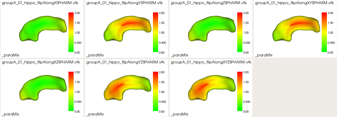
Figure : Visualization in ShapePopulationViewer of the different flips applied on *SPHARM model.
Running SPHARM-PDM

Click on the Run ShapeAnalysisModule button, to run the three steps on the provided inputs.
Progress bars will indicate when the computation is done and if the computation for each case was completed with or without error.

If the module was completed with errors, the step which was completed with errors is indicated and the errors can be displayed by clicking on the little arrows:

3D Slicer’s Error Log can also be used for debugging if the module was completed with errors. To open it, click on the red icon at the bottom right.

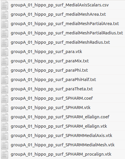
The outputs files for each step of SPHARM-PDM are stored in three folders in the output directory previously selected:

Quality control using ShapePopulationViewer
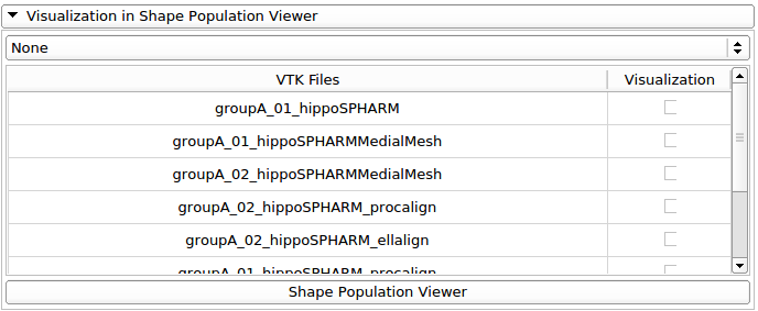
If Shape Population Viewer is installed, the Visualization tab will be enabled:
Note : ShapePopulationViewer is installed by default in SlicerSALT
The selection of the SPHARM outputs which will be displayed in Shape Population Viewer can be done thanks to the checkable combobox or with the checkbox corresponding to them:
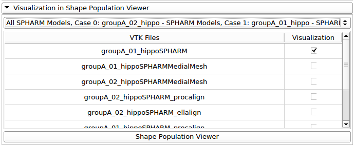
Run Shape Population Viewer by clicking on the Shape Population Viewer button:

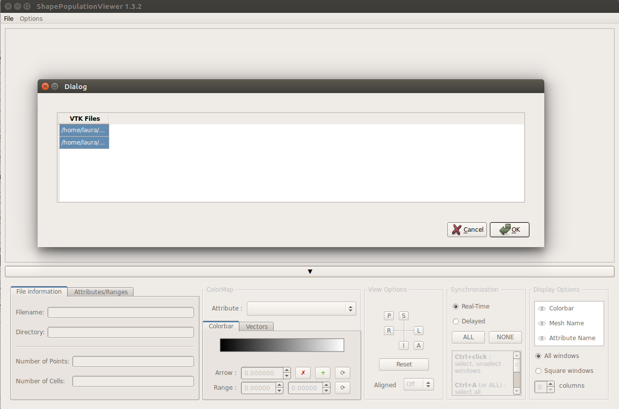
To display the selected models in Shape Population Viewer , click on VTK Files and then Ok :
To display the different color maps on the meshes, use the comboBox Attributes:

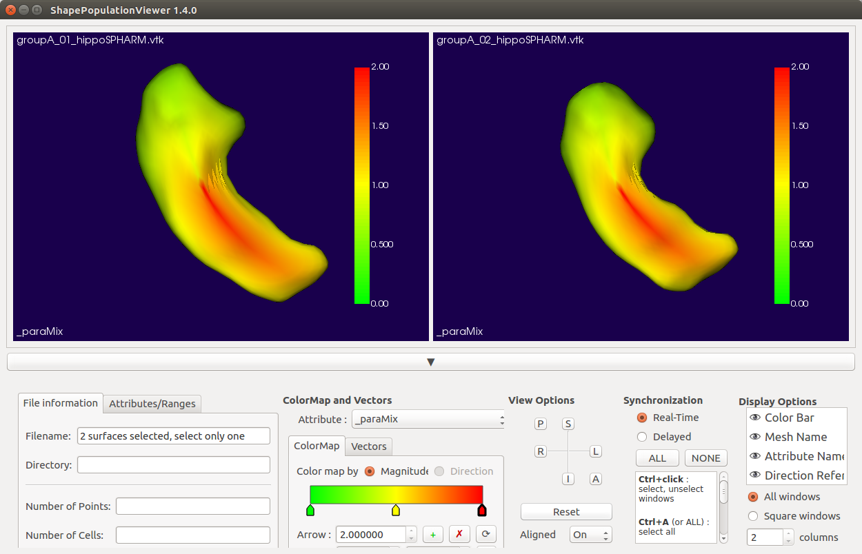
Figure : Visualization in ShapePopulationViewer of two *SPHARM models with the phi spherical parameter representation
Example: This view shows the phi correspondences between the files.
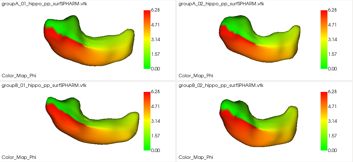
Quality control of the correspondences is performed using the color-coded parameterization information.
Equally colored areas represent equal corresponding area.
groupA_01_hippo_pp_surf_SPHARM.vtk
groupA_01_hippo_pp_surf_SPHARM.vtk
groupA_01_hippo_pp_surf_SPHARM.vtk
groupA_01_hippo_pp_surf_SPHARM.vtk
Figure : Visualization in ShapePopulationViewer of multiples *SPHARM shapes displaying paraPhi color map
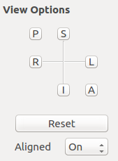
Only data sets with Procrustes alignment information are automatically aligned in Shape Population Viewer .
For data sets without Procrustes alignment:
Under View Options , set Aligned to __On __ to align the data set using file information.
For more information about using Shape Population Viewer tool, consult the ShapePopulationViewer tutorial by Alexis Girault.
Quality control using Models module
Models can be viewed in 3D Slicer or SlicerSALT by dragging and dropping the files or by using the Data button in the toolbar to search for the file.
When importing the VTK file, select the Model Option :

When the VTK file has been imported, it will be visualized in the Scene View (or the 3D View). Switch to the Models Module to change the display settings of the VTK model.

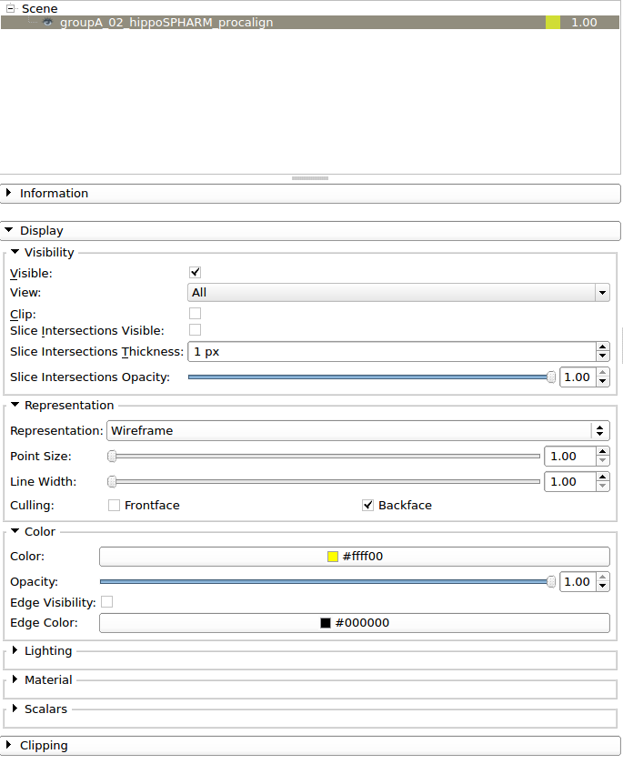
Hide/show the model by clicking on the eye icon
To change the display properties of the VTK file, first select the file from the Scene window in the Models Module
Change the representation of the model mesh. For example, Wireframe representation will display the meshing of the model
Change the color of the mesh from the default gray color
Change the opacity of the mesh
Acknowledgements - Resources - Questions
- The SPHARM-PDM developers gratefully acknowledge funding for this project provided by NIH NIBIB R01EB021391 (Shape Analysis Toolbox for Medical Image Computing Projects), as well as the Slicer community.
- Github repository:
- Forums:
- Papers:
- Lateral ventricle morphology analysis via mean latitude axis.
- Framework for the Statistical Shape Analysis of Brain Structures using SPHARM\-PDM
- For other remarks or questions, please email: beatriz.paniagua@kitware.com